The Useless Box
After some deliberation, we selected the infamous "Useless Box" for TPE's first project. The rationale behind this choice consisted mostly of uncertainty about how we wanted to structure our project development pipeline, and what exactly each project would entail. We felt that choosing a fairly simple project would allow us to explore various methodologies and identify strong and weak points to implement in later, more complex endeavors.
In addition, as inexperience is the spirit of TPE, the "Useless Box" allows us time to develop fundamental skills that will be directly applicable to our future projects (circuit board development, CAD, assembly, etc.) While both Tyler and I have a bit of previous experience in our respective fields, we definitely needed a bit of time to refresh and refine basal skills.
Project Introduction
Great, but what exactly is a Useless Box? Fundamentally, it's just a box that, when it is toggled to its "on" state, will in some way toggle itself back to the "off" state. Fairly useless, eh?
It is a fairly simplistic device that can take on many forms, with varying levels of theatrics for the action it performs to turn itself off. Our rendition is the classical variant, whose fundamental components include an arm, switch, and lid. When the user toggles the switch to the "on" position, the lid is lifted via an actuator and an arm emerges from inside of the box, flicking the switch to the "off" position, retracting back into the box, with the lid returning to the closed position to conceal it.
Stages of Development
We are going to be entirely upfront and admit that the timeline for this project has become incredibly drawn-out and inefficient. The specific details of that will be elaborated on in the rest of this section, however, the chief takeaway is that it revealed many points of improvement that will allow us to manage future projects more effectively.
Planning
We focused on two main points during the initial conceptualization process of this project: product functionality, and material requirements. The very first thing we did was open up a Google Doc and simply listed out everything that the box was going to do and how. How would the arm work? Where would we place it? How expressive do we want it to be? How is the lid going to work? Do we want visible hinges?
After a fairly thorough look at functionality, we created a BoM (Bill of Materials) to list all of the materials we needed and their costs. This gave us a central location to manage all of the components of the box and ensured that we wouldn't forget anything as we started making purchases.
The first iteration of the box consisted of two SG90 Servos, one driving the lid, and another for the arm, an outer construction of wood, a PCB (printed circuit board) with an ATTiny45 microcontroller for the logic, all powered by four AA batteries.
PCB Design & Manufacturing
For those who have no prior experience with embedded electronics, please see this article, which gives a high-level overview of what embedded electronics entails. While the scope of this topic is large, we hope through several completed projects that we will be able to properly demonstrate all of the important aspects.
We attempted to compartmentalize this project into a few discrete systems: the physical control system (actuators), digital control system (electronics), and mechanical system (construction, actuated components, etc). For the most part, this worked fairly well, however, we treated it as steps in series rather than parallelizing our workflow, which is the first major point of improvement that this project highlighted.
The development of the PCB was the first major step in the process, and also one that contributed to most of the "waiting" time. Once the design was completed and submitted to our manufacturer, there was a lead time of several weeks in which we didn't perform any other tasks, we were just in a very wasteful "waiting" state. Our rationale behind this was mainly "Well, we can't actually assemble anything until we have the PCB anyway, so why bother working on other components until we have it?" We were far too ingrained in this rigid timeline that required a preceding step to be completed in order for the next to begin. We will avoid this in the future and try to work on things in parallel whenever possible.
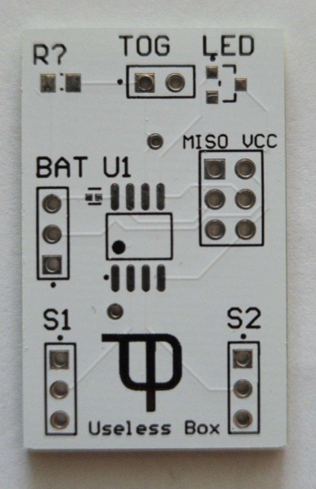
Anyway, onto the actual development of the PCB; it consists of 8 main components:
- Microcontroller (ATTiny 45)
- Two servo outputs (Power, Ground, and Data)
- Battery input (6V, 3V, Ground)
- Toggle switch input
- LED indicator light
- Six-pin programming interface
- Pull-down resistor
The basic operation of the circuit is as follows: the servo data lines are connected to GPIO (general-purpose input-output) pins on the microcontroller, the toggle switch is also connected to a GPIO pin, and when the switch is set to ON, that line goes HIGH (carries 5V rather than 0V) which the microcontroller is listening for, and once this occurs, signals are sent over to the servos, which cause them to perform their programmed sequence of actions.
If you're interested in the exact schematic, you can download the PDF below.
We're utilizing the Altium Designer software for our PCB development needs, it is an industry-standard professional CAD software for PCB / circuit design and we are grateful to receive a free license through the University of Michigan. There are plenty of online tutorials on YouTube, but we found this one particularly helpful.
Below is an image of the completed and final version of the PCB.
Box Design & Manufacturing
Taking a bit of a break on the controls side of things, we now move to the design of the box itself! As we hadn't yet been exposed to much CAD, this project posed a great opportunity to get our feet wet in the world of design. As previously mentioned, this project isn't exactly complicated in terms of its construction, so it serves as a good starting point for learning how to create CAD models and iterate through different designs.
We chose Fusion 360 for our CAD software, in part due to a free license provided by the University of Michigan, but also because it is relatively beginner-friendly compared to other software, which we plan to eventually migrate to.
Design Process
The first step in the design process consisted of rough sketching, a bit of online research was done for some inspiration from other useless boxes, and from there we built the foundation of our design.
Once we had a solid idea in mind, we began modeling it in Fusion. Although this project presents itself as quite simple, there are actually a fair amount of moving parts that go into it. Starting with the lid, the design consisted of two different segments: a stationary one that houses the switch, and one on a pivot to allow the arm to flick the switch.
Then, we had to design the core box structure itself, which went through, undoubtedly, the most iterations. What started out as a completely hollow box, eventually turned into a half-hollow box with a raised platform so the battery holders could be accessed from the outside and the servo that activated the switch could be elevated.
Next came the arms: the lifting arm for the pivoting lid was one of the simplest parts we had to make and we didn't have much trouble with it, however the activation arm for the switch went through some iteration because it was originally designed for a small SG90 servo which proved to lack the torque needed to flip the switch, so it had to be completely redone for a larger, high-torque servo.
Material Choice & Manufacturing
While we originally planned on making the box out of wood, we quickly realized that it would be much easier and more efficient to 3D print it. Making multiple iterations out of wood living in a tiny dorm was not something we could easily manage and wasn't worth the hassle, so we instead decided to utilize the free 3D printing services provided by the University of Michigan's Shapiro Design Lab.
That seemed like a great idea, and we think it was, however, our print did not turn out as planned, and given the fact that it took 18 hours and the process for getting a time slot was quite long, we really didn't want to test our luck and use it again. We waited until spring break, to inevitably have several more failed prints. One of the biggest frustrations of this project definitely stems from issues with 3D printing, as we were just not in an ideal situation to facilitate it.
We eventually got a print we could call "good enough", as spring break came to a close and we had to move back to campus. Once we got back to campus we realized one small mistake: we had forgotten the activation arm, throwing our timeline even more off track.
Ultimately, we just decided to wait until the winter semester was over so we could have easy access to 3D printers and more efficiently work on our design. That phase of the project is still in progress. Next year we hope to bring a 3D printer with us on campus to our apartment which will avoid a lot of these issues.
Programming
As with any programming project, it starts with a high-level algorithm: detect when the switch has been flicked, open the lid, advance the arm to flick the switch the other way, retract the arm, and finally close the lid. Adding some timing variation can create a bit of expressiveness and personification in the device (a slower lid opening with a very quick arm movement can resemble grumpiness or anger, for example).
After we've drawn out our algorithm, we can move on to the actual implementation!
The first step in deciding how to write our implementation is to choose the programming language that we are going to write it in. Typically, languages can be ranked by how "high-level" or "low-level" they are; this is in reference to how much "abstraction" the language provides atop the actual machine code that runs directly on the processor. Some familiar low-level languages may include C and C++. While some high-level languages include Python, Java, and JavaScript. For our cases, we're writing code directly onto a microcontroller without any underlying operating system (so-called "bare-metal" programming). In such a case, we want to aim for a low-level language as higher-level ones typically require an environment with an operating system to utilize most of their features.
We had a few options here, but we decided to take the easy way out for this project. The Arduino project easily supports our microcontroller of choice, and has a plethora of libraries that add a layer of abstraction to make embedded systems programming simpler and more time efficient. It runs on C++ with its own integrated libraries, so that is ultimately the avenue we took.
Our alternative is something we want to explore for future projects but will require a bit of time to flesh out: embedded programming with Rust. Rust is relatively new compared to languages such as C and C++, and is generally highly regarded in the programming community, with very attractive features that emphasize safety (preventing unwanted bugs), performance, and productivity. Embedded programming with Rust is still in the early stages but it is something TPE will likely explore in the future, so stay tuned.
In addition to writing the program in C++, we are also utilizing the PlatformIO development platform which provides a repository of libraries and builds atop the Arduino platform for our use case.
Our project uses the PciManager and PrecisionServo libraries. PciManager handles the pin-change interrupts, which simply halts the code whenever one of the output pins receives a change in signal and runs a function. PrecisionServo provides an interface to interact with the servos that run both the arm and lid.
Code Walkthrough
Next, we will walk through each aspect of the code and what it does, however, keep in mind that this project is not complete, and therefore neither is the code.
// servo positions (deg) //
#define LID_CLOSED 628
#define LID_OPEN 628
#define ARM_RETRACT 628
#define ARM_EXTEND 628

// pins //
#define LED 0
#define TOG 1
#define LID 0
#define ARM 0
First, we define some values at the top of the file that are used throughout the program. Currently, they just hold garbage values until we get proper positions and pin numbers.
PrecisionServo* lid;
PrecisionServo* arm;

void switchFlick(byte change);
void execute_sequence(int lid_ms, int arm_ms);

PciListenerImp listener(TOG, switchFlick);
Then, we create some objects and define some functions that will make writing the code a bit easier, we won't get too much into this part but just know that these functions will be defined in a bit. It is also important to note that the listener will trigger the switchFlick function whenever the TOG pin is changed.
void setup() {
    ServoManager::setup(2);

    lid = ServoManager::createServo(LID);
    arm = ServoManager::createServo(ARM);

    lid->setSetting(SERVO_MEDIUM_PRECISE);
    arm->setSetting(SERVO_MEDIUM_PRECISE);

    pinMode(LED, OUTPUT);
    pinMode(TOG, INPUT);

    PciManager.registerListener(&listener);

    digitalWrite(LED, HIGH);
    delay(500);
    digitalWrite(LED, LOW);
}
Initialize the objects we previously created, and blink the LED to convey that we are at the end of the setup sequence. setup is the first function that runs in our program and it only runs once.
void set_wait(PrecisionServo* s, int target) {
    s->setTarget(target);
    ServoManager::waitUntilFinished();
}
This is a so-called "helper function" that abstracts away what otherwise would be repetitive code, it instructs the servo to move to a certain position and then halts the code until the servo is finished moving.
void execute_sequence(int lid_ms, int arm_ms) {
    set_wait(lid, LID_OPEN);
    set_wait(arm, ARM_EXTEND);
    set_wait(arm, ARM_RETRACT);
    set_wait(lid, LID_CLOSED);
}
This is the main part of our program, it defines the action sequence that occurs when the switch is flicked. Notice the parameters lid_ms and arm_ms? In the final iteration of this code, we hope to add the aforementioned expressiveness by randomly generating these values and controlling the speed of the servos. For now, we just move the servos to the pre-defined positions in sequence.
void switchFlick(byte change) {
    if (change == CHANGEKIND_LOW_TO_HIGH) {
        execute_sequence(0, 0);
    }
}
Finally, we define the switchFlick function, which the listener calls whenever a switch flick is detected. It ensures that the signal change was from low to high to avoid being called when the switch is flicked off by the device itself, and simply calls the execute_sequence function.
That's it! As you can see, the code for this device is very simple.
Concluding Remarks
This concludes our introduction of the Useless Box project; we anticipate future project logs to be much finer in scope and more frequent. We have some exciting projects coming up, so stay tuned! Also keep your eye out for Useless Box updates as we wrap the project up in the next couple of weeks.